VIRTUAL SWITCHING SYSTEM
Introduction:
This blog explains Virtual Switching System (VSS).
What is a Virtual Switching System (VSS)?
In general network switches were used as standalone device. It is a single chassis which has a control plane and multiple data planes. The control plane uses a configuration file to operate and handle the traffic. With VSS it is possible to bundle two physical chassis into logically as a single device.
Why VSS?
Virtual switching system feature helps in various ways in the network. The key advantages are it eliminates the need for next hop redundancy protocol, helps to achieve multi-chassis EtherChannel, configuration overhead on multiple chassis, easy to manage etc.
Where VSS?
VSS is feasible only on Cisco multilayer switches, i.e. high-end Data centre switches like catalyst 6500 and 4500 series. These series are used as Core switches in the Data centres where high speed data transfers are required, and very low latency network is required.
Detailed Explanation:
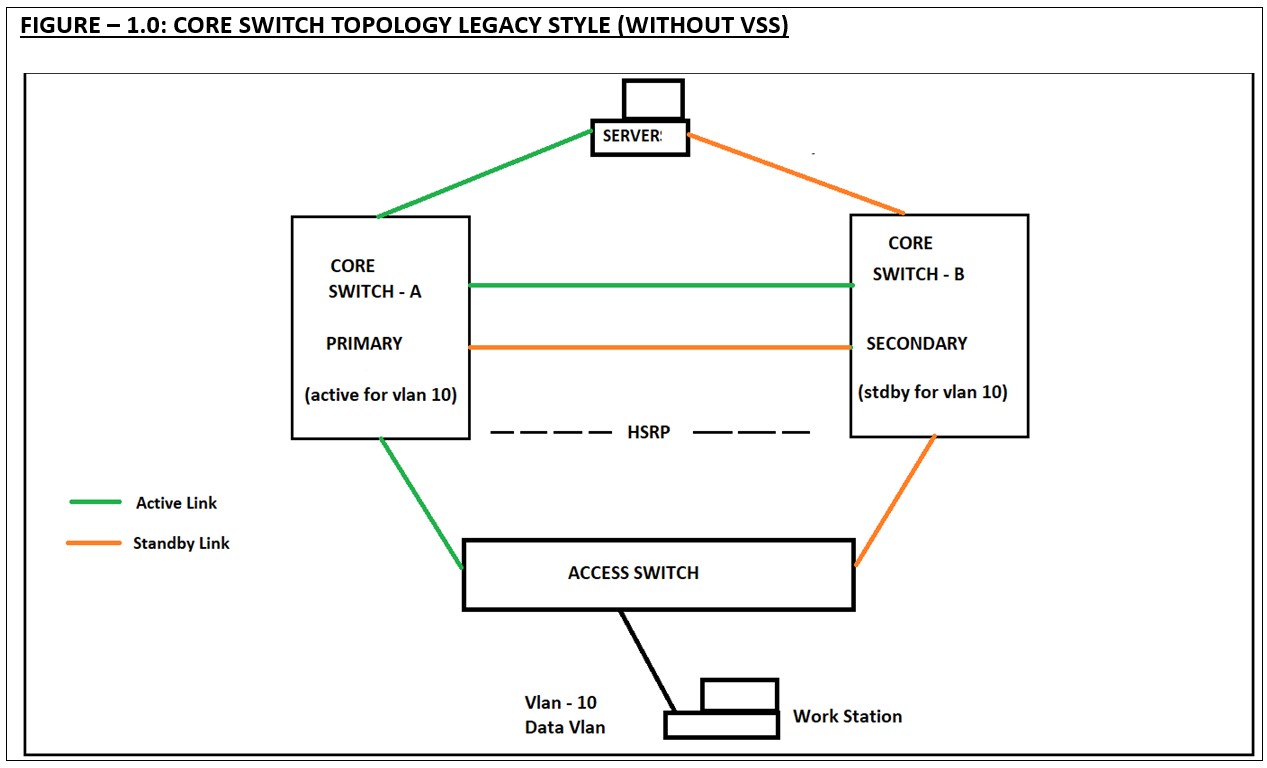
In this section we will see the detailed explanation about the VSS. Before, understanding about VSS, let’s see how the legacy Data centre core switches were built.
| FIGURE – 1.0: CORE SWITCH TOPOLOGY LEGACY STYLE (WITHOUT VSS)
|
- In the above topology only one link will handle the traffic from both the access switch and server standpoint. The other link will be unused until if there is an issue with the primary link or the primary switch.
- Both the core switch will use their own control plane and data plane.
- Both the switches will use individual configuration file. But these two configuration files should be uniform, which means, any configuration change requires to be applied in both the switches. This is the configuration overhead.
- If the network admin misses the configuration on the standby switch, during the failure of the primary core switch, the standby may not function as like the primary core switch.
|
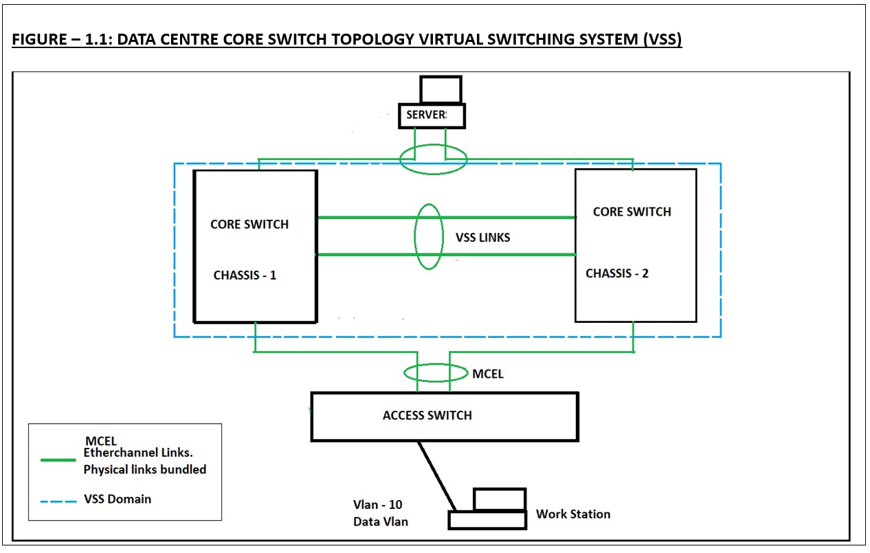
FIGURE – 1.1: DATA CENTRE CORE SWITCH TOPOLOGY VIRTUAL SWITCHING SYSTEM (VSS)
|
HOW VSS WORKS?
- In the above figure 1.1 both the core switches are uplinked and configured for VSS.
- Both the core switches will be on one VSS domain.
- There will be only one control plane, which means only one configuration file.
- Both the switches are bundled together and acts as logically as a single switch.
- This will further help in bundling the multiple physical up links from the servers and the access switches to be bundled and work as logically a single link.
- This will benefit in higher bandwidth, high availability.
- The next hop redundancy protocols such as HSRP, VRRP are no longer required.
- Configuration changes are applied as like to a single switch.
- In the event of the primary switch failure, the traffic switch over time is very less compared to the legacy setup.
Conclusion
Hope, I explained VSS in a simpler way. Please note that VSS is only for Cisco Data Centre switches like catalyst 6500 and 4500 series.
| Tail piece:
Does the below question raise for you? Since VSS is only for high end Cisco Data centre switches, Is there something similar for the access switches? YES, there is. STACKING is the feature that is used to configure multiple access switches into logically single switch which uses master/ member concept. |


