Everything you need to know about establishing secure, private connectivity between VCNs in OCI
Introduction
If you’re running applications across multiple Virtual Cloud Networks (VCNs) in Oracle Cloud Infrastructure, you’ve probably wondered how to enable private communication between them. By default, instances in different VCNs can’t talk to each other, even within the same region. That’s where the Local Peering Gateway comes in.
In this guide, I’ll walk you through the complete process of setting up a Local Peering Gateway to connect two VCNs, allowing your instances to communicate securely over Oracle’s private network.
What You’ll Learn
- How to create and configure Local Peering Gateways
- Setting up routing and security rules for cross-VCN communication
- Testing and verifying your peering connection
- Troubleshooting common issues
Our Example Setup
For this walkthrough, we’ll be connecting: – VCN-1: 10.10.0.0/24 – VCN-2: 172.17.0.0/24
Before You Begin
Requirements
Make sure you have:
- Two VCNs created in the same OCI region
- Non-overlapping CIDR blocks (this is critical!)
- IAM permissions: manage virtual-network-family
- Access to OCI Cloud Console
- Basic understanding of VCN routing and security concepts
Critical Limitations to Know
1. No Overlapping CIDR Blocks
This is non-negotiable. If your VCNs have overlapping IP address ranges, peering simply won’t work. Plan your network architecture accordingly.
2. No Transit Routing
Local Peering Gateway doesn’t support transit routing. This is one of the most important limitations to understand when designing your OCI network architecture, and it catches many people by surprise.
What is Transit Routing?
Transit routing (also called transitive routing) is when traffic passes through one network to reach another network. Think of it like a highway system where you drive through City B to get from City A to City C.
In networking terms, transit routing means VCN-B would act as a “middleman” or “relay point” forwarding traffic between VCN-A and VCN-C.
Why OCI Blocks Transit Routing:
Oracle explicitly prevents transit routing through Local Peering Gateways for several important reasons:
- Security: Prevents unintended network paths and unauthorized access
- Performance: Eliminates extra network hops that would slow down traffic
- Simplicity: Makes network behavior predictable and easier to troubleshoot
- Cost control: Prevents accidental data transfer charges through intermediate VCNs
Detailed Example – What Actually Happens:
Let’s walk through a real-world scenario with three VCNs:
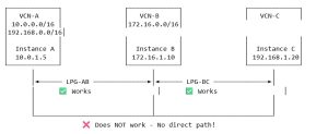
VCN-A (10.0.0.0/16) – Your web application tier
VCN-B (172.16.0.0/16) – Your middleware/services tier
VCN-C (192.168.0.0/16) – Your database tier
You create two peering connections: – VCN-A ↔ VCN-B (LPG-AB) – VCN-B ↔ VCN-C (LPG-BC)
What Actually Works:
✅ VCN-A to VCN-B: Direct communication works perfectly – Instance in VCN-A (10.0.1.5) can reach instance in VCN-B (172.16.1.10) – Route exists: 172.16.0.0/16 → LPG-AB – Packets flow directly through the peering gateway
✅ VCN-B to VCN-C: Direct communication works perfectly – Instance in VCN-B (172.16.1.10) can reach instance in VCN-C (192.168.1.20) – Route exists: 192.168.0.0/16 → LPG-BC – Packets flow directly through the peering gateway
✅ VCN-B to Both: The middle VCN can talk to everyone – VCN-B can reach both VCN-A and VCN-C – It has direct peering connections to both
What Absolutely Does NOT Work:
❌ VCN-A to VCN-C: No communication possible (through VCN-B) – Instance in VCN-A (10.0.1.5) cannot reach instance in VCN-C (192.168.1.20) – Even though VCN-B is connected to both – Even if you add a route in VCN-A: 192.168.0.0/16 → LPG-AB – The packets will be dropped at VCN-B
Why the Packets Get Dropped:
Here’s what happens step-by-step when an instance in VCN-A tries to reach VCN-C:
Step 1: Instance in VCN-A (10.0.1.5) sends packet to 192.168.1.20
↓
Step 2: VCN-A’s route table says: “192.168.0.0/16 → LPG-AB”
↓
Step 3: Packet arrives at VCN-B through LPG-AB
↓
Step 4: VCN-B checks: “Is this packet destined for ME (172.16.0.0/16)?”
Answer: NO (it’s for 192.168.1.20)
↓
Step 5: VCN-B drops the packet 🗑️
Result: Connection times out, no response
Why doesn’t VCN-B forward it to VCN-C?
Because OCI’s Local Peering Gateway is designed as a point-to-point connection, not a router. It doesn’t perform IP forwarding between different peering connections.
Visual Representation:
Real-World Impact – Multi-VCN Connectivity:
Let’s say you need to connect multiple VCNs. Here’s how the number of required peering connections grows:
| VCNs | Required Connections | Peering Pairs |
| 2 | 1 | A↔B |
| 3 | 3 | A↔B, B↔C, A↔C |
| 4 | 6 | A↔B, A↔C, A↔D, B↔C, B↔D, C↔D |
| 5 | 10 | Every pair needs direct connection |
| 6 | 15 | This gets complicated fast! |
Formula: For N VCNs that all need to communicate: N × (N-1) / 2 peering connections
The Maximum Limit Problem:
Remember: Maximum 10 Local Peering Gateways per VCN
This means: – A single VCN can directly peer with at most 10 other VCNs – If you have 11 VCNs that all need to communicate, LPG alone won’t work – You’ll hit the limit very quickly in complex environments
Common Mistake – The Hub-and-Spoke Trap:
Many architects try to design this:
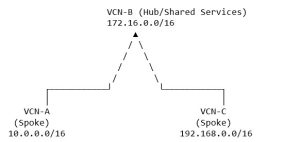
Assumption: “VCN-A and VCN-C can both reach shared services in VCN-B, and that’s all I need.”
Reality Check: What if VCN-A needs to access VCN-C later? – You’ll need to create a third direct peering connection – Your “hub” architecture doesn’t actually simplify anything – You still end up with a full mesh
Correct Solutions for Multi-VCN Architectures:
Option 1: Full Mesh with Local Peering Gateway
Create direct peering between every VCN pair.
✅ Good for: – 2-4 VCNs – Simple, predictable environments – When you need maximum performance (no extra hops)
❌ Bad for: – 5+ VCNs (gets unmanageable) – Environments that change frequently – When you might hit the 10 LPG limit
Option 2: Dynamic Routing Gateway (DRG)
Use Oracle’s DRG, which does support transit routing.

All VCNs can communicate through the DRG hub!
✅ Good for: – 4+ VCNs – Hub-and-spoke architectures – On-premises connectivity – Cross-region VCN connectivity – Environments that will grow
❌ Bad for: – Very simple 2-VCN setups (LPG is simpler) – Cost-sensitive projects (DRG has additional costs)
Option 3: Consolidate into Fewer VCNs
Use subnets within a single VCN instead of separate VCNs.
✅ Good for: – When VCNs are separated for organizational reasons, not technical – Simpler management – No peering overhead
❌ Bad for: – When you need true network isolation – Multi-tenant environments – Different security requirements per environment
Option 4: Network Security Groups (NSGs) for Isolation
Keep resources in one VCN, use NSGs for security boundaries.
✅ Good for: – Micro-segmentation within a single VCN – Granular security controls – Avoiding VCN sprawl
❌ Bad for: – When you need true network separation – Compliance requirements for network isolation
Decision Tree – What Should You Use?
Start: Do you need to connect VCNs?
│
├─► Only 2 VCNs?
│ └─► Use Local Peering Gateway ✅
│
├─► 3-4 VCNs, all same region, simple topology?
│ └─► Use Local Peering Gateway (full mesh) ✅
│
├─► 5+ VCNs OR need hub-and-spoke OR will grow?
│ └─► Use Dynamic Routing Gateway (DRG) ✅
│
├─► Need cross-region connectivity?
│ └─► Use DRG ✅
│
└─► Need on-premises connectivity?
└─► Use DRG ✅
Key Takeaway:
Think of Local Peering Gateway connections like direct phone calls between two people: – Alice can call Bob directly – Bob can call Charlie directly – But Alice cannot route her call through Bob’s phone to reach Charlie – Alice needs Charlie’s number to call him directly
Similarly, each VCN pair that needs to communicate must have its own direct peering connection. There’s no “forwarding” or “relaying” through an intermediate VCN.
3. Service Limits
- Maximum 10 Local Peering Gateways per VCN
- Each LPG can only peer with one other LPG
- LPGs must be in the same region
Part 1: Creating the Local Peering Gateways
Step 1: Create LPG for VCN-1 (LPG-A)
- Navigate to your first VCN
- Go to: OCI Cloud Console → Networking → Virtual Cloud Networks
- Select your compartment
- Click on VCN-1
- Select Gateways from the left menu
- Create the gateway
- Scroll down to the Local Peering Gateways section
- Click Create Local Peering Gateway
- Enter a descriptive name (e.g., “LPG-A” or “LPG-to-VCN2”)
- Click Create Local Peering Gateway
Step 2: Create LPG for VCN-2 (LPG-B)
Repeat the same process for VCN-2:
- Navigate to VCN-2 → Gateways
- Click Create Local Peering Gateway
- Name it “LPG-B” (or “LPG-to-VCN1”)
- Click Create
Important: Both LPGs must be created before you can establish the peering connection.
Part 2: Establishing the Peering Connection
Now that both gateways exist, let’s connect them:
- Navigate back to VCN-1’s gateways
- Find LPG-A in the list
- Click the three dots menu (⋮)
- Select Establish Peering Connection
- Configure the connection
- Compartment: Select the compartment where LPG-B resides
- Local Peering Gateway: Select LPG-B from the dropdown
- Click Establish Peering Connection
- Verify the status
- The status should change to: “Peered – Connected to a peer”
- This should happen almost instantly
🎉 Your gateways are now connected! But we’re not done yet…
Part 3: Configuring Route Tables
For traffic to flow between VCNs, we need to tell each VCN how to reach the other network.
Configure VCN-1 Route Table
- Navigate to: VCN-1 → Routing → Default Route Table
- Click Add Route Rules
- Configure:
- Target Type: Local Peering Gateway
- Destination CIDR Block: 17.0.0/24 (VCN-2’s CIDR)
- Target Local Peering Gateway: Select LPG-A
- Click Add Route Rules
Configure VCN-2 Route Table
- Navigate to: VCN-2 → Routing → Default Route Table
- Click Add Route Rules
- Configure:
- Target Type: Local Peering Gateway
- Destination CIDR Block: 10.0.0/24 (VCN-1’s CIDR)
- Target Local Peering Gateway: Select LPG-B
- Click Add Route Rules
Part 4: Configuring Security Rules
Routing tells the network where to send traffic, but security rules control whether that traffic is allowed. Let’s open up the necessary ports.
Ingress Rules (Incoming Traffic)
Add Rule to VCN-1
- Navigate to: VCN-1 → Default Security List → Security Rules
- Click Add Ingress Rule
- For SSH access, configure:
- Source Type: CIDR
- Source CIDR: 17.0.0/24
- IP Protocol: SSH (TCP/22)
- Description: “Allow SSH from VCN-2”
- Click Add Ingress Rule
Add Rule to VCN-2
Repeat for VCN-2: – Source CIDR: 10.10.0.0/24 – IP Protocol: SSH (TCP/22) – Description: “Allow SSH from VCN-1”
Egress Rules (Outgoing Traffic)
By default, OCI allows all egress traffic. However, if you’ve restricted egress rules, you’ll need to add explicit rules.
Check your existing rules first: If you already have a rule for “Destination: 0.0.0.0/0, Protocol: All”, you don’t need additional egress rules.
If you need to add egress rules:
VCN-1 Egress Rule
- Destination CIDR: 17.0.0/24
- IP Protocol: All Protocols
VCN-2 Egress Rule
- Destination CIDR: 10.0.0/24
- IP Protocol: All Protocols
Part 5: Adding ICMP for Ping Testing
ICMP (the protocol used by ping) is essential for testing connectivity. Let’s enable it.
Add ICMP to VCN-1
- Navigate to: VCN-1 → Default Security List → Security Rules
- Click Add Ingress Rule
- Configure:
- Source Type: CIDR
- Source CIDR: 17.0.0/24
- IP Protocol: ICMP
- Type: All types (or specific types like 3, 8 for Echo Request)
- Description: “Allow ICMP from VCN-2”
- Click Add Ingress Rule
Add ICMP to VCN-2
Repeat with: – Source CIDR: 10.10.0.0/24 – Description: “Allow ICMP from VCN-1”
Part 6: Additional Protocols (Optional)
Depending on your application needs, you might want to add more protocols. Here are some common examples:
HTTP/HTTPS Access
To allow web traffic: – Source CIDR: Remote VCN CIDR – IP Protocol: TCP – Destination Port: 80 (HTTP) or 443 (HTTPS)
Database Access
For database connectivity (e.g., Oracle Database): – Source CIDR: Remote VCN CIDR – IP Protocol: TCP – Destination Port: 1521 (Oracle) or 3306 (MySQL) or 5432 (PostgreSQL)
Common Application Ports Reference
| Service | Protocol | Port(s) |
| SSH | TCP | 22 |
| HTTP | TCP | 80 |
| HTTPS | TCP | 443 |
| Oracle DB | TCP | 1521 |
| MySQL | TCP | 3306 |
| PostgreSQL | TCP | 5432 |
| Redis | TCP | 6379 |
| MongoDB | TCP | 27017 |
| RDP | TCP | 3389 |
| DNS | UDP | 53 |
Testing Your Configuration
Now for the moment of truth! Let’s verify everything is working.
1. Verify Peering Status
Check in the OCI Console: – Navigate to VCN-1 → Gateways → Local Peering Gateways – Status should show: “Peered – Connected to a peer” – Repeat for VCN-2’s LPG
2. Check Route Tables
Verify your routing: – VCN-1 should have a route to 172.17.0.0/24 via LPG-A – VCN-2 should have a route to 10.10.0.0/24 via LPG-B
3. Verify Security Rules
Double-check that: – VCN-1 allows ingress from 172.17.0.0/24 – VCN-2 allows ingress from 10.10.0.0/24 – Required protocols (SSH, ICMP) are configured
4. Test Connectivity
Ping Test
From an instance in VCN-1:
ping <VCN-2-instance-private-IP>
From an instance in VCN-2:
ping <VCN-1-instance-private-IP>
You should see replies! If not, jump to the troubleshooting section below.
SSH Test
From VCN-1:
ssh opc@<VCN-2-instance-private-IP>
Application Test
Test your specific application ports to ensure they’re accessible.
Troubleshooting Guide
Common Issues and Solutions
Problem: Can’t ping between instances
Possible causes: 1. ICMP not enabled in security lists – Solution: Add ICMP ingress rules to both security lists
- OS-level firewall blocking traffic
- Check instance firewall:
- sudo iptables -L-n-v
sudo firewall-cmd –list-all
- Route table misconfigured
- Verify destination CIDRs and LPG targets
Problem: Peering status stuck on “Pending”
Possible causes: 1. Compartment permissions issue – Verify you have the correct IAM policies
- One side not accepted
- Peering requires action from both VCNs
Problem: “Overlapping CIDR” error
Solution: – You cannot peer VCNs with overlapping CIDR blocks – You’ll need to recreate one VCN with a non-overlapping CIDR range
Problem: Peering works but specific ports don’t
Diagnostic steps: 1. Test port connectivity: bash telnet <remote-instance-private-ip> 22 nc -zv <remote-instance-private-ip> 22
- Check security list rules for the specific port
- Check instance-level firewall:
- sudo iptables -L-n-v|grep<port>
- Verify the service is listening:
- sudo netstat -tlnp|grep<port>
Useful Diagnostic Commands
Check routing:
ip route show
route -n
Test connectivity:
ping <remote-ip>
traceroute <remote-ip>
Check open ports:
sudo netstat -tlnp
sudo ss -tlnp
Rolling Back (If Needed)
If you need to disconnect the peering or remove the configuration, follow these steps in reverse order:
1. Remove Security Rules
- Delete ingress rules for remote VCN CIDRs from both security lists
- Delete egress rules if you added them
- Delete ICMP rules
2. Remove Route Rules
- Delete route rules pointing to remote VCN CIDRs from both route tables
3. Terminate Peering Connection
- Navigate to VCN-1 → Gateways → Local Peering Gateways
- Click the three dots menu (⋮) next to LPG-A
- Select “Terminate Peering Connection”
- Confirm
⚠️ Warning: Terminating the peering will immediately stop all communication between VCNs. Make sure to migrate or stop dependent applications first.
4. Delete LPGs (Optional)
If you want to completely remove the gateways: – You must terminate the peering first – Then delete each LPG from its respective VCN
Note: An LPG in “Peered” state cannot be deleted.
5. Verify Rollback
- Check that peering status shows “New” or LPGs are deleted
- Verify route rules are removed
- Test that instances can no longer communicate
Security Best Practices
As you implement Local Peering Gateway, keep these security principles in mind:
1. Principle of Least Privilege
Only open the ports and protocols you actually need. Don’t default to “allow all” unless absolutely necessary.
2. Use Specific CIDR Blocks
Avoid using 0.0.0.0/0 as source in your security rules. Always specify the actual remote VCN CIDR block.
3. Document Everything
- Keep a record of all security rule changes
- Document the purpose of each rule
- Maintain a change log
4. Regular Audits
- Periodically review your security list configurations
- Remove rules that are no longer needed
- Check for overly permissive rules
5. Consider Network Security Groups
For more granular control, consider using Network Security Groups (NSGs) instead of security lists. NSGs offer: – More flexibility in rule management – Easier to apply to specific resources – Better suited for complex network architectures
Key Takeaways
Let’s recap the important points:
✅ CIDR blocks must not overlap – This is the most common reason peering fails
✅ No transit routing – Each VCN pair needs a direct connection
✅ Both routing and security matter – Route tables show where to go, security rules control what’s allowed
✅ Test methodically – Start with ICMP, then SSH, then application-specific ports
✅ Security first – Only open what you need, when you need it
Additional Resources
Oracle Documentation
- Local VCN Peering Official Documentation
- OCI Networking Best Practices Guide
- Security Lists Documentation
Related Topics
- VCN Creation and Configuration
- Network Security Groups (NSGs)
- Remote VCN Peering (for cross-region connectivity)
- Dynamic Routing Gateway (DRG) for more complex topologies
Conclusion
Setting up a Local Peering Gateway between OCI VCNs isn’t complicated, but it does require attention to detail. By following this guide, you should now have private, secure connectivity between your VCNs.
Remember: – Plan your CIDR blocks carefully from the start – Configure both routing and security in both VCNs – Test thoroughly before moving to production – Document your configuration for future reference
Have questions or run into issues? Feel free to reach out in the comments below, or consult the Oracle Cloud documentation for more details.
Happy networking! 🚀